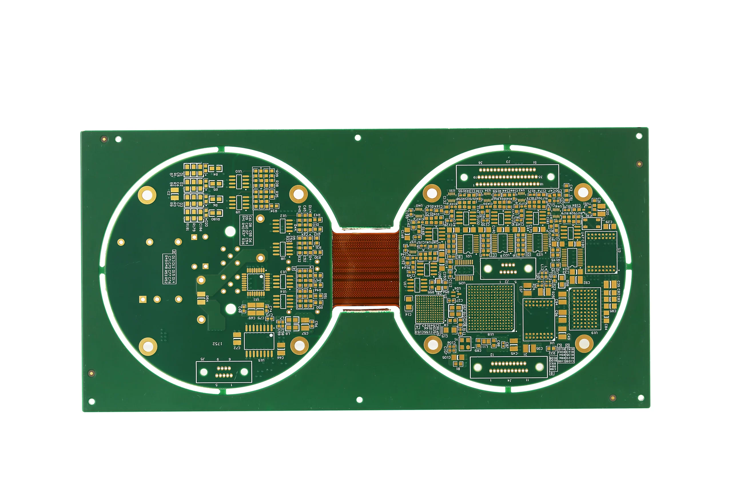


Rigid-Flex PCBs, which combine rigid and flexible substrates in a single board, have gained immense popularity in various high-performance applications such as wearable devices, medical instruments, automotive electronics, and more. While these boards offer numerous advantages in terms of compactness, flexibility, and durability, maintaining signal integrity can be a significant challenge due to their complex construction. The transition between rigid and flexible sections, along with high-frequency signal requirements, can lead to signal degradation, crosstalk, and other issues. In this blog, we’ll explore several strategies for optimizing the signal integrity of Rigid-Flex PCBs, ensuring reliable performance in demanding environments.
Signal integrity refers to the quality and accuracy of electrical signals transmitted across a PCB. High-speed signals can suffer from a variety of problems, including attenuation, reflection, noise, and distortion. For Rigid-Flex PCBs, these problems can become more pronounced due to the differing materials used in the rigid and flexible sections, as well as the mechanical bending that occurs in flexible areas. Optimizing signal integrity is crucial to ensuring that the PCB performs reliably without data loss or errors, especially in applications requiring high-frequency transmissions.
Before diving into solutions, it’s important to understand the challenges posed by Rigid-Flex PCBs in terms of signal integrity:
Differential Material Properties: Rigid and flexible substrates have different electrical properties. Rigid PCBs typically use materials like FR4, while flexible parts use polyimide or similar polymers. These materials may have different dielectric constants (Dk) and coefficients of thermal expansion (CTE), which can affect the impedance and overall signal quality.
Impedance Discontinuities: As the signal transitions between the rigid and flexible sections of the PCB, impedance mismatches can occur. These discontinuities can cause signal reflections, resulting in data loss or interference.
Mechanical Stress: The flexible areas of the PCB are prone to bending and flexing, which can change the layout and physical dimensions of the traces. This deformation can lead to variations in impedance and signal attenuation, negatively affecting signal quality.
Crosstalk and Noise: In densely packed designs, the proximity of signal traces can lead to crosstalk, where signals from adjacent traces interfere with each other. Additionally, noise from external sources or power supply fluctuations can affect the signal quality.
High-Frequency Requirements: Many modern devices require high-speed signal transmission. As the frequency of signals increases, maintaining signal integrity becomes more challenging, particularly in Rigid-Flex PCBs with their mixed material stack-up and mechanical stresses.
To ensure the optimal performance of Rigid-Flex PCBs, several design and manufacturing strategies can be employed to mitigate the challenges mentioned above. Here are some of the best practices:
The selection of materials for both the rigid and flexible portions of the PCB is critical for optimizing signal integrity. The dielectric constant (Dk) of materials affects the signal speed and impedance, so it’s essential to use materials that have consistent Dk values across the entire board. For example, polyimide used in flexible areas should have similar electrical properties to the rigid FR4 material to minimize impedance mismatches.
Moreover, using materials with low loss tangents (Df) can reduce signal attenuation, ensuring that high-frequency signals maintain their integrity across the board.
Impedance control is vital for high-speed designs, especially for differential pairs and high-frequency signals. Ensuring consistent trace width and spacing is essential to maintain a controlled impedance throughout the PCB. In Rigid-Flex designs, careful attention should be paid to the transitions between the rigid and flexible sections of the board, as this is where impedance discontinuities are most likely to occur.
To address this, manufacturers can use stripline or microstrip design techniques, where the signal traces are sandwiched between conductive layers or placed on a layer above the ground plane. These structures help maintain consistent impedance and prevent signal reflections.
A solid ground plane is essential to maintain signal integrity, particularly in high-speed designs. By providing a low-impedance return path for signals, a ground plane can reduce noise and crosstalk between signal traces. Additionally, incorporating power planes in the rigid sections of the PCB ensures stable power delivery and reduces the risk of ground bounce.
In flexible sections, it may not always be feasible to use traditional ground planes. In such cases, designers can use floating ground techniques or incorporate via-in-pad designs to ensure that the flexible section remains electrically stable.
The flexible portion of the PCB is subject to bending and mechanical stress, which can impact the layout and signal quality. Designers can minimize the impact of bending by using wider traces, increasing trace spacing, and ensuring that the bending radius is large enough to avoid excessive deformation of the traces.
By carefully considering the bend radius during the design phase, engineers can reduce the likelihood of trace fractures or impedance variations in the flexible areas, ensuring consistent signal transmission.
To reduce the impact of external noise and electromagnetic interference (EMI), designers can use shielding techniques such as incorporating ground traces around sensitive signal traces or using external shielding layers. These shielding techniques are especially useful in applications like automotive or medical devices, where the PCB might be exposed to significant electrical noise.
Additionally, keeping signal traces as short as possible and separating high-speed signals from noisy power lines or other signal traces can minimize the risk of crosstalk and noise coupling.
Before manufacturing the PCB, it’s crucial to simulate the signal integrity using specialized software tools. Tools like HyperLynx or Ansys HFSS can model the behavior of signals in the PCB design and help identify potential issues such as impedance mismatches, signal reflections, or noise problems. These simulations can guide the design process, allowing engineers to make adjustments before the physical prototype is built.
Maintaining optimal signal integrity in Rigid-Flex PCBs is a challenging but crucial task for high-performance electronic systems. By carefully selecting materials, controlling impedance, incorporating effective shielding, and minimizing mechanical stress on the flexible sections, designers can ensure that the board delivers reliable performance even in demanding applications. With the right design strategies and simulation tools, signal integrity can be optimized, allowing Rigid-Flex PCBs to meet the needs of the most advanced electronic devices.
Simplify Your PCB Journey with XPCB Limited
XPCB Limited simplifies the PCB process for you. With our quick-turnaround prototyping and turnkey PCBA services, we ensure that your projects move forward smoothly and efficiently. Trust our commitment to quality and timeliness as we help you bring your designs to life. Choose XPCB Limited for a hassle-free PCB experience.
XPCB Limited is a premium PCB & PCBA manufacturer based in China.
We specialize in multilayer flexible circuits, rigid-flex PCB, HDI PCB, and Rogers PCB.
Quick-turn PCB prototyping is our specialty. Demanding project is our advantage.
Tel : +86-136-3163-3671
Fax : +86-755-2301 2705
Email : [email protected]
© 2024 - XPCB Limited All Right Reserve
