


As an integral part of the whole machine, a printed circuit board generally cannot constitute an electronic product, and there is bound to be an external connection problem. For example, electrical connections are required between printed boards, printed boards and external components, printed boards and equipment panels. It is one of the important contents of the printed board design to select the connection with the best coordination of reliability, manufacturability and economy. There are many ways of external connection, which should be selected flexibly according to different characteristics.
The advantages of this connection method are simplicity, low cost, high reliability, and can avoid failure caused by poor contact. The disadvantage is that interchange and maintenance are not convenient enough. This method is generally suitable for the case where the components have fewer external leads.
This method does not require any connectors, as long as the external connection points on the PCB printed board are directly welded to the components or other parts outside the board with wires. For example, the horn and battery box in the radio.
Pay attention to the interconnection welding of the circuit board.
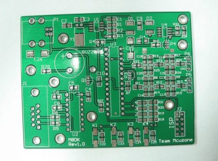
(1) The soldering wire pads should be as close as possible to the edge of the PCB printed board and arranged in a uniform size to facilitate soldering and maintenance.
(2) In order to improve the mechanical strength of the wire connection and avoid pulling off the pad or printed wire due to the wire being pulled, drill holes should be drilled near the solder joints on the PCB printed board to allow the wires to pass through the soldering surface of the printed board. Go through the through hole and then insert the pad hole from the component surface for soldering.
(3) Arrange or bundle the wires neatly, and fix them to the board with wire clips or other fasteners to prevent the wires from breaking due to movement.
2. PCB Cable Welding
The two PCB boards are connected by a flat cable, which is reliable and not prone to connection errors, and the relative position of the two PCB boards is not restricted.
The printed boards are directly welded. This method is often used for connecting two printed boards at a 90 degree angle. After connection, it becomes an integral PCB printed board part.
In more complicated instruments and equipment, connector connections are often used. This “building block” structure not only ensures the quality of mass production of products, reduces the cost of the system, and provides convenience for debugging and maintenance. When the equipment fails, the maintenance personnel do not need to check to the component level, that is, check the cause of the failure and trace the source to the specific component. This work takes a considerable amount of time. As long as it is judged which board is abnormal. It can be replaced immediately, troubleshooting in the shortest time, shortening downtime, and improving equipment utilization. The replaced circuit board can be repaired within ample time and used as a spare part after repair.
1. Printed Board Socket
In more complex instruments and equipment, this type of connection is often used. This method is to make a printed plug from the edge of the PCB board, and the plug part is designed according to the size of the socket, the number of contacts, the distance of the contacts, the position of the positioning hole, etc., to match the special PCB board socket.
When making the board, the plug part needs to be gold-plated to improve the wear resistance and reduce the contact resistance. This method is easy to assemble, has good interchangeability and maintenance performance, and is suitable for standardized mass production. The disadvantage is that the cost of the printed board is increased, and the manufacturing precision and process requirements of the printed board are higher; the reliability is slightly worse, and the contact is often poor due to the oxidation of the plug part or the aging of the socket reed. In order to improve the reliability of external connections, the same lead wire is often led out in parallel through the contacts on the same side or on both sides of the circuit board.
The PCB board socket connection method is often used for products with multi-board structure. The socket and the printed board or the bottom plate have two types: reed type and pin type.
2. Standard pin connection
This method can be used for external connection of printed boards, especially pin connections are often used in small instruments. The two printed boards are connected through standard pins. The two printed boards are generally parallel or perpendicular, which is easy to achieve mass production.
XPCB Limited is a manufacturer specializing in the production of high-precision double-sided, multi-layer and impedance, blind buried vias, and thick copper circuit boards. The products cover HDI, thick copper, backplanes, rigid-flex combined, buried capacitance and buried resistance, Golden Finger and other types of circuit boards, which can meet the needs of customers for various products.
XPCB Limited is a premium PCB & PCBA manufacturer based in China.
We specialize in multilayer flexible circuits, rigid-flex PCB, HDI PCB, and Rogers PCB.
Quick-turn PCB prototyping is our specialty. Demanding project is our advantage.
Tel : +86-136-3163-3671
Fax : +86-755-2301 2705
Email : [email protected]
© 2023 - XPCB Limited All Right Reserve
