


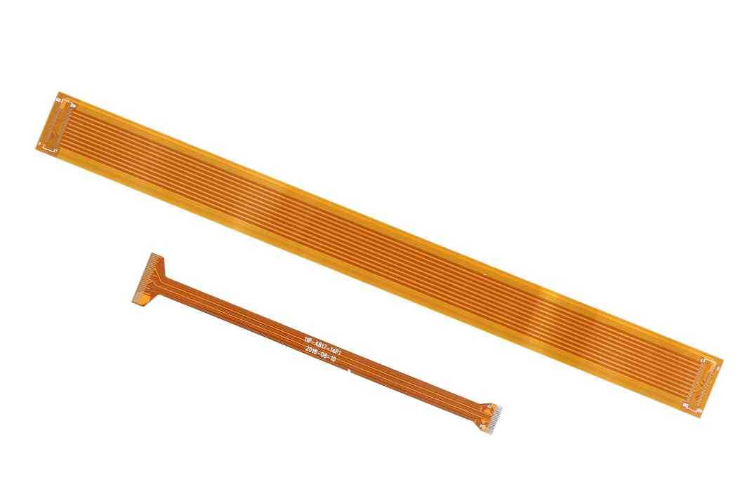
Flexible Printed Circuit Board is a form of circuit made on the flexible cut-off surface, and it can have a cover layer or not (usually used to protect the FPC circuit). Since Flex PCB can be bent, folded or repetitively moved in a variety of ways, compared with ordinary rigid PCB (pcb), it has the advantages of lightness, thinness, flexibility, etc., so its application is more and more extensive, so we are designing What do you need to pay attention to? Let’s talk about it in detail below.
In the design, FPC often needs to be used in conjunction with PCB. In the connection between the two, board-to-board connectors, connectors with gold fingers, HOTBAR, soft and hard boards, and manual soldering are usually used for connection. For different applications, the designer can adopt the corresponding connection method.
In actual applications, determine whether ESD shielding is required according to the application needs. When the FPC flexibility requirements are not high, it can be implemented with solid copper and thick media. When the flexibility requirements are high, it can be realized by using copper skin grid and conductive silver paste.
Due to the flexibility of the FPC, it is easy to break when under stress, so some special means are needed for FPC protection.
The commonly used methods are:
1. The minimum radius of the inner corner on the flexible contour is 1.6mm. The larger the radius, the higher the reliability and the stronger the tear resistance. At the corner of the shape, a trace near the edge of the board can be added to prevent the FPC from being torn.
2. The crack or slot on the FPC must end in a round hole with a diameter of not less than 1.5mm. This requirement is also required when the two adjacent parts of the FPC need to be moved separately.
3. In order to achieve better flexibility, the bending area needs to be selected in a uniform width area, and try to avoid the FPC width change and uneven wiring density in the bending area.
4. Stiffener, also known as stiffener, is mainly used to obtain external support. The materials used are PI, Polyester, glass fiber, polymer materials, aluminum sheets, steel sheets, etc. Reasonable design of the position, area and material of the reinforcing plate has a great effect on avoiding FPC tearing.
5. In the multi-layer FPC design, the area that needs to be bent frequently during the use of the product needs to be designed with air gap layers. Try to use thin PI materials to increase the softness of the FPC and prevent the FPC from breaking during repeated bending.
6. When space permits, a double-sided tape fixing area should be designed at the junction of the golden finger and the connector to prevent the golden finger and the connector from falling off during the bending process.
7. The FPC positioning silk screen line should be designed at the connection between the FPC and the connector to prevent the FPC from skewing and improper insertion during the assembly process. Conducive to production inspections.
XPCB Limited is a premium PCB & PCBA manufacturer based in China.
We specialize in multilayer flexible circuits, rigid-flex PCB, HDI PCB, and Rogers PCB.
Quick-turn PCB prototyping is our specialty. Demanding project is our advantage.
Tel : +86-136-3163-3671
Fax : +86-755-2301 2705
Email : [email protected]
© 2023 - XPCB Limited All Right Reserve
