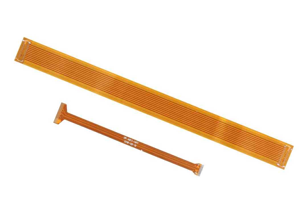


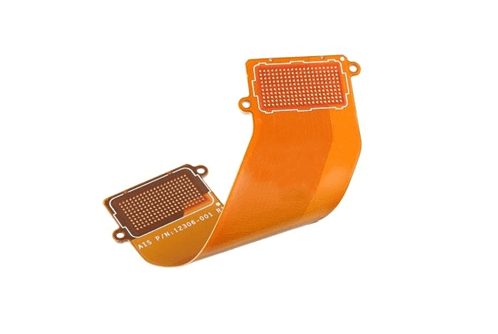
Do you know the structure of flexible PCB
In the structure of flexible PCB, the materials are insulation film, adhesive and conductor.
The insulation film forms the base layer of the circuit, and the adhesive attaches the copper foil to the insulation layer. In a multilayer design, it is then bonded to the inner layer. They are also used as a protective covering to insulate the circuit from dust and moisture and to reduce stress during deflection. Copper foil forms a conductive layer.
In some flexible circuits, rigid parts made of aluminum or stainless steel provide dimensional stability, physical support for the placement of components and wires, and stress relief.
The adhesive bonded the rigid part to the flexible circuit. Another material that is sometimes used in flexible circuits is the bonding layer, which is formed by coating the sides of an insulating film with an adhesive. Bonding laminates provide environmental protection and electronic insulation, and the ability to eliminate a single layer of film, as well as multiple layers with fewer bonding layers.
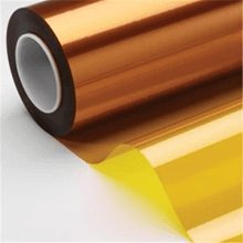
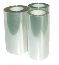
There are many types of insulating film materials, but the most commonly used are polyimide and polyester materials. Currently, nearly 80 percent of all flexible PCB manufacturers in the United States use polyimide film materials, and about 20 percent use polyester film materials.
Polyimide materials have a flammability, stable geometrical dimension and has high resistance to tear strength, and have the ability to withstand the welding temperature.
Polyester, also known as Polyethylene terephthalate (PET), and its physical properties similar to the polyimide, have lower dielectric constant, absorption of moisture is very small, but not resistant to high temperature. The melting point of polyesters is 250 ° c and the glass conversion temperature (Tg) is 80 ° c, which limits their use in applications where extensive end welding is required. They are rigid for low temperature applications. Nevertheless, they are suitable for use in products such as phones and others that do not require exposure to harsh environments.
Polyimide insulation film is usually combined with polyimide or acrylic adhesive, polyester insulation materials are generally combined with polyester adhesive. The advantage of combining with materials with the same properties can be the dimensional stability after dry welding or after multiple lamination cycles. Other important properties in adhesives are low dielectric constant, high insulation resistance, high glass transition temperature (Tg), and low moisture absorption.
In addition to being used to bond insulating films to conductive materials, adhesives can also be used as a covering, protective coating, and covering coating. The main difference between the two is in the way they are applied. Screen printing technique used for coating of adhesive.
Not all lamination structures contain adhesives, and lamination without adhesives results in thinner circuits and greater flexibility. Compared with the lamination structure based on adhesive, it has better thermal conductivity. It can be used in the working environment where the flexible circuit based on the adhesive lamination structure cannot be used due to the thin structure characteristics of the flexible circuit without adhesive and the improved thermal conductivity due to the elimination of the thermal resistance of the adhesive.
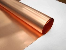
Copper foil is suitable for use in flexible circuits, it can use the electric deposition (ED), or rolled copper foil (RA foil). Electrodeposited copper foil has a shiny surface on one side, while the processed surface on the other side is dull and dull. It is a flexible material that can be made into many thicknesses and widths, and the dull side of ED copper foil is often specially treated to improve its bonding ability.
Rolled copper foil not only has flexibility, but also has the characteristics of hard and smooth, which is suitable for application in the case of dynamic deflection.
Flexible circuit board layout and optimization scheme
To integrate all data of the FPC (mechanical matching, design criteria, line(circuit) type and geometric structure interconnection form), paper patterns shall be made simultaneously for matching and subsequent items inspection:
Keeping the line in the correct sequence and gradually changing into the dense area is a relatively headache for FPC design. In most cases, the designer cannot configure the pin or contact very freely and flexibly.
In a practical world, FPC design can only be added later in the product plan, most of which happens after the wiring configuration has been determined, and there are few opportunities for rearrangement. There are bound to be many situations where the left line has to reach the right pin or junction, and PTH is a more general solution that allows reconfiguration of the contact relationship using interlayer connectivity.
For designers who do not want to use PTH, the available solutions are external folding, refolding, double-sided jumper combination, crossing connection and so on.
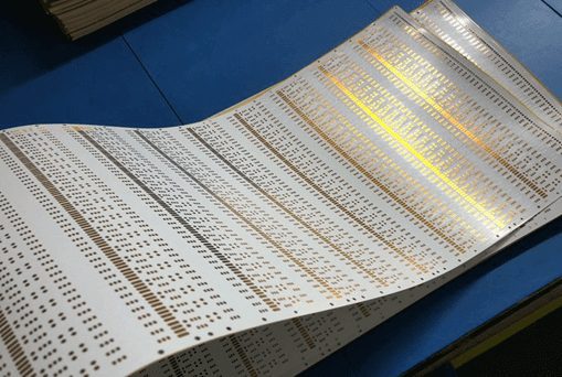
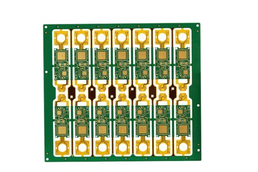
From the point of view of design, the design of a piece of FLEXIBLE circuit board is quite exquisite, but relatively high cost is also required for the construction of a unit of flexible circuit board. How many small flexible circuit boards gathered on the whole production size of flexible circuit board can improve the production efficiency more effectively, so it will be cheaper in execution.
It is important to note that if the technology and quality standards allow multiple contacts to be combined on a single terminal, the design can break down the complex circuit design and simplify to a separate flexible circuit board with more common terminals.
The small flexible circuit board can be configured into panel according to the type for convenience and testing, which can further reduce the cost.
Four common types of flexible circuit boards
1. Single-sided flexible PCB
The cost of single side flexible board is the lowest. When the electrical performance requirements are not high, and can be single-sided wiring, should choose a single-sided flexible plate. This most common form has found commercial applications, such as jet cartridges for printers and memory for computers.
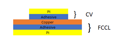
The single-sided flexible board has a layer of conductive graph etched by chemical etching, and the conductive graph layer on the flexible insulating substrate is rolled copper foil. Insulation substrates used for flexible assembly may be polyimide (Kapton), polyethylene terephthalate (PET), aromatic amide fiber paper (Nomex), and polyvinyl chloride (PVC).
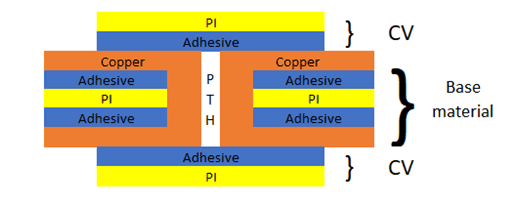
2. Double-sided flexible board
The double-sided flexible plate is a conductive pattern etched on two sides of the substrate. Metallized holes connect the two sides of the insulating material to form a conductive path to meet the design and use of flexural function. The covering film can protect the single and double sides of the wire and indicate the placement of the element.

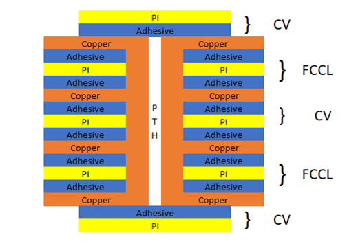
3. Multi-layer flexible board
Multi-layer flexible board is to layer three or more layers of single-sided flexible circuit board or double-sided flexible circuit board together, through drilling, electroplating to form a metal hole, formed a conductive path between different layers. In this way, no complicated welding process is needed. Although the number of conductive layers designed for this flexible type can be unlimited, the interaction of assembly size, number of layers, and flexibility should be taken into account when designing the layout to ensure assembly convenience.
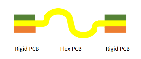
4. Rigid-flex board
The traditional rigid-flex board is composed of selective formation compression of rigid and flexible substrates. The structure is compact, forming conductive connection with metallized holes.
Considering the reliability and price factors, the factory should try to maintain as few layers as possible.
HDI Rigid-Flex PCB: High Density combined printed circuit board (HDI) is a high-end printed circuit board product that aims to meet the growing demand of electronic products toward miniaturization, high-frequency high-speed, and multiactivity.
HDI rigid-flexible joint board combines the advantages of popular HDI board and rigid-flex board, and promotes the development of high integration and high intelligence in the design and production of electronic system. It has been widely used in high-end electronics such as aerospace techniques, medical equipment and consumer products.

X-pcb is a leading factory of prototypes and volume pcb in Shenzhen. We can offers a wide range of different printed circuit boards to our customers in the world.
Some Capabilities:
Soldermask bridge between solder dam: 4 mil (0.10 mm)
Minimun soldermask annular: 1.5 mil (0.038 mm)
Plugged hole size: 0.15 mm – 0.5 mm
Special material: HTG FR4, high frequency (Rogers, Teflon, ARLON, TYCONIC), halogen free, different material mixing laminating.
Special techniques: Blind and buried vias (min hole size is 0.1 mm), high layer with heavy copper.
XPCB Limited is a premium PCB & PCBA manufacturer based in China.
We specialize in multilayer flexible circuits, rigid-flex PCB, HDI PCB, and Rogers PCB.
Quick-turn PCB prototyping is our specialty. Demanding project is our advantage.
Tel : +86-136-3163-3671
Fax : +86-755-2301 2705
Email : [email protected]
© 2023 - XPCB Limited All Right Reserve
