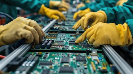


Most smt chip components are reflow soldered, while through-hole components are wave soldered, though it is not a hard and fast rule. In through-hole pcb assembly technology, the board is wave soldered to form a strong solder joint even when the component is inserted into the drilled hole. Usually, through-hole components are inserted manually.
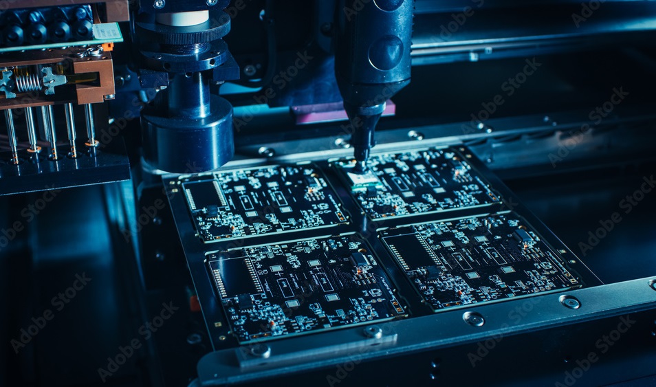
For smt components, solder paste is applied directly to the pads, holding the leads of the component in one position. When the PCB is passed through the special reflow, the solder paste is reflowed. Here, a solid solder joint is formed. If you are using a hybrid type, you will need to use both wave soldering and reflow soldering. There are ready automatic pick-and-place machines that can reliably handle the various components.
The benefits of smt and through-hole
Let us understand why smt machining types are often used:
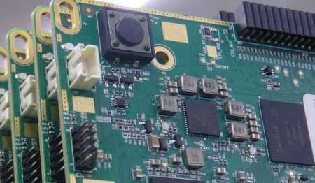
Size: By default, smt components or parts are small or miniature. No drilling is required. This looks clean and attractive, especially in the age of smaller electronics board sizes.
Availability: Today, smt has taken over from through-hole components. They are smaller, replacing resistors, capacitors and other through-hole components that dominate pcba patching has taken over more and more.
Performance: The use of smaller components in the SMD allows electrical signals to be transmitted over shorter distances. This also reduces the signal flight time.
Cost-effectiveness: SMT parts are often cheaper than through-hole parts, so let’s take a quick look at the benefits of through-hole parts.
Availability: If you need a larger part for a high power application, it may be difficult to find an SMT equivalent. Through-hole parts are readily available.
Strength: SMT solder joints can break if the part has to be subjected to constant pressure. In this case, components such as connectors, switches and other interface components need the strength that is effectively provided by the leads from the solder to the drilled hole.
Power: SMT is not a good choice for high power circuits because SMT soldering makes it difficult to achieve strong solder joints. Through-hole technology therefore provides greater mechanical strength for thermal stability, high voltage and mechanical stability.
XPCB Limited is a premium PCB & PCBA manufacturer based in China.
We specialize in multilayer flexible circuits, rigid-flex PCB, HDI PCB, and Rogers PCB.
Quick-turn PCB prototyping is our specialty. Demanding project is our advantage.
Tel : +86-136-3163-3671
Fax : +86-755-2301 2705
Email : [email protected]
© 2024 - XPCB Limited All Right Reserve
