


For electrical test purposes, circuit board faults may be defined as test system measurement results other than those programmed to be representative of a good board. The faults detected may or may not impact the functionality of the circuit board, though in most cases they will. Some guidelines may prove useful when more specific guidance from the original specifier or designer is lacking. Gross shorts and opens in a circuit are likely to cause problems. Will an electrical test system find all the faults? The definition of “all the faults” is too subjective.
The electrical test system will not detect all faults related to aesthetics, annular rings, layer-to-layer registration, etc. unless they present an effect measurable by the test system. Further, the electrical measurement employed, type of test fixture, test program generation method, and end-user requirements vary too widely to state broadly that electrical testing will find all the faults. For purposes of the following discussion, it is worthwhile to clarify the distinction between a defect and a fault.
A fault is a test system designation for an item that does not meet the expected criteria. A defect refers specifically to the board and a defect in its design, fabrication, appearance, etc. Not all defects can be detected by the test system.
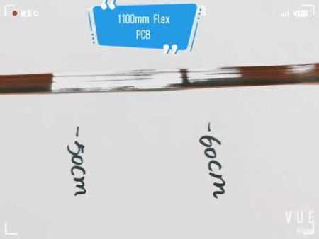
Image 1: Circuit board fault
Shorts, hard shorts, or short circuits are defined here as erroneous (undesired and unexpected) low-resistance connections between two or more networks or isolated points, typically exhibiting a fairly low electrical resistance value. Shorts are reported as failures of the isolation test of the product. Shorts are produced in a variety of ways, including exposure problems, under etching, contaminated photo tools, poor alignment of layers, defective raw material, and improper solder leveling.
Opens represent an absence of expected circuit continuity, or in other words, a missing connection. This divides a circuit network such that the network is split or divided into two or more pieces. Opens are reported as failures of the continuity testing of the product. Opens are produced in a variety of ways, including over etching, under plating, contaminated photo tools, contaminated raw material, layer registration errors, and mechanical damage. A common problem during electrical testing is “false open” errors, typically the result of localized contamination on the product or test probe that prevents proper connection to the test system.
Of particular concern in testing substrates employing microvias are latent defects (those which may appear after test during subsequent substrate assembly processing). Examples are improperly formed conductors at stress points where cracks may form during thermal or mechanical stresses of assembly. Small HDI features are less tolerant of such defects. These may be completely undetectable at the time of test, or limited examples may be detected by especially sensitive ohmic measurements able to detect a limited conductor cross section where a future open circuit may occur. Frequent observation of such defects indicates the need for process changes if field failures are to be avoided.
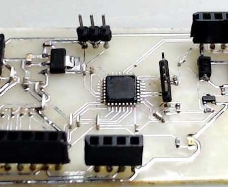
Image 2: electronic test pcba
Many circuits produced today are required to operate at very wide bandwidths. Examples include fast microprocessors, fast general digital circuits, RF amplifiers in wireless devices, etc. Just as we must use a proper type of cable to connect a television antenna to a TV receiver, it is important for specific RF characteristics to be maintained in interconnections between components of fast electronic circuits on printed wiring boards. One parameter commonly specified and measured is the RF transmission line impedance of the signal traces. This parameter is strongly affected by the materials used in fabricating the board, the trace thickness and width, and the spacing from ground planes and adjacent signals.
A common method of measuring RF impedance is to employ TDR. The TDR measurement provides a statement of RF impedance as a function of distance along the trace. (Distance and time are related here, as the electric signal flows through the board at velocities approaching the speed of light.) TDR testing is often performed on a test coupon attached to the product during manufacture and subsequently disconnected. TDR testing on actual product traces is also done on selected traces, but is complicated by the need for a trace length of several inches, uninterrupted by branches or other constructions. Common values for RF impedance on circuit boards range from the low tens of ohms to several hundred ohms.
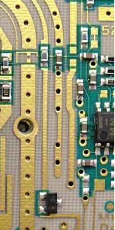
Image 3: RF Hole
RF impedance should not be confused with ordinary direct current (DC) resistance and cannot be measured with common ohmmeters, even though the same unit of measure—the ohm—is used. RF parameters of interconnections can also be characterized in the frequency domain using instruments referred to as network analyzers, but this method is not common in bare board testing. Requirements for RF impedance testing are more commonly applied as signal frequencies exceed 100 MHz.
Discover a World of Possibilities with XPCB Limited
At XPCB Limited, we’re here to help you explore new horizons. Our advanced PCB manufacturing, rapid prototyping, and turnkey PCBA solutions make it easy for you to turn your ideas into reality. Trust us to deliver excellence and reliability every step of the way. Join us and experience the power of innovation with XPCB Limited by your side.
XPCB Limited is a premium PCB & PCBA manufacturer based in China.
We specialize in multilayer flexible circuits, rigid-flex PCB, HDI PCB, and Rogers PCB.
Quick-turn PCB prototyping is our specialty. Demanding project is our advantage.
Tel : +86-136-3163-3671
Fax : +86-755-2301 2705
Email : [email protected]
© 2023 - XPCB Limited All Right Reserve
